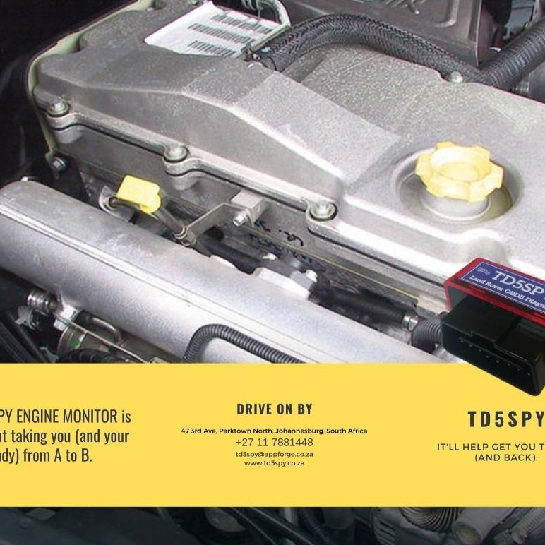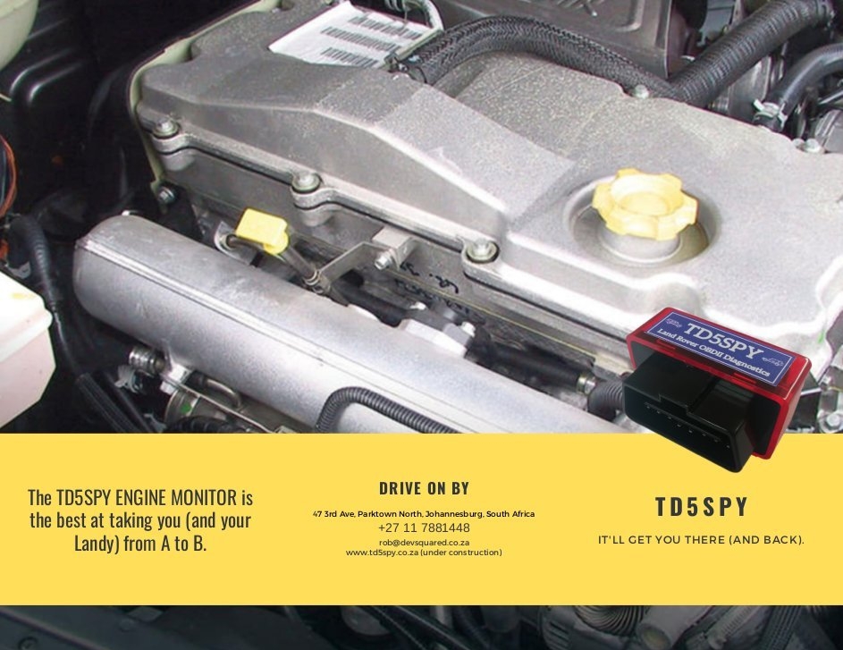
Defender TD5 allSPY Installation Guide
Installation Guide
How to install an allSPY into a Defender TD5
allSPY INSTALLATION GUIDE (DEFENDER TD5)
Install the TD5SPY application on your mobile phone (see related guide).
allSPY supplied kit items
-
allSPY control unit
-
EGT probe, compression fitting, adapter plate and 2 x M8 bolts
-
3 x temperature sensors and 3 x 2.5m 2 core(brown and blue wires) sensor wires.
-
1 x 100PSI pressure sensor and 1 x 2m 3 core (brown [+5V], blue [GND], green/yellow [OUT]) sensor wire
-
Adapters
-
M10x1 to 1/8NPT for Engine Oil Pressure
-
M16x1.5 to 1/8NPT for Engine Oil Temp
-
M16x1.5 to 1/8NPT for Gearbox Oil Temp (Auto gearbox only)
-
M14x1.5 to 1/8NPT for Transfer Oil Temp
allSPY INSTALLATION INSTRUCTIONS
-
The allSPY unit can be installed under the drivers seat and stuck against the side wall (or other convenient location using double sided tape. Make all connections and test the installation before fixing the unit to the side wall. Feed all wires through the large grommet to the allSPY control unit. Power (+12V and GND) can be fed through from the battery box compartment. Do not connect power to the allSPY unit until all other connections are made and checked. Drain engine oil.
-
Remove the front (EGR blanking) plate from the exhaust manifold and fit the EGT probe with the supplied adaptor plate. Slide the Probe completely in to the compression fitting. Do not over tighten the fitting. Feed and secure the shrouded cable along the front of the engine following existing wires through to the allSPY unit. Do not over tighten the EGT connection screws.
-
Temporarily fix the Coolant Level Detector to the side/rear of the coolant expansion tank. Extend the Brown (+5v), Blue (GND) and Yellow (OUTPUT) wires through to the allSPY unit and connect as per connection diagram. Leave the black wire disconnected.
-
When fitting sensors to the adapters, use a bit of thread lock to assist in providing a seal. Fit (and test seal) sensors before fitting adapters to the vehicle.
-
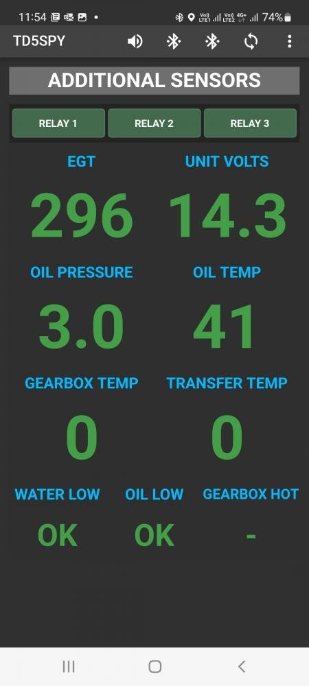
Remove the oil pressure switch and fit the Oil Pressure Sensor using the 1/8NPT to M10x1 adaptor. Attach the supplied sensor cable and feed around the back of the engine through to the allSPY unit and connect as per connection diagram. Extend and connect the disconnected oil pressure switch lead to the allSPY unit. (INP1 and RELAY 2 NC) (oil pressure switch emulate mode enabled).
-
Fit Oil Temp Sensor to engine sump drain plug with adaptor M16x1.5 to 1/8NPT. Connect supplied 2 core cable and route through to allSPY unit.
-
Fit Gearbox Oil Temp Sensor to gearbox sump fill plug with adaptor M16x1.5 to 1/8NPT. Connect supplied 2 core cable and route through to allSPY unit. (Auto gearbox only)
-
Fit Transfer Oil Temp Sensor to blanking plug on transfer box with adaptor M14.15 to 1/8NPT. Connect supplied 2 core cable and route through to allSPY unit.
-
Once all sensors connected, fit the Warning Buzzer between OUT3 (black) and +5V (red). Connect vehicle earth to allSPY unit GND [BATT-]. Connect GND to Relay 1 and Relay 2 COM. Connect vehicle +12V to +12V input of the allSPY unit [BATT +] via an in-line 1 amp fuse (not supplied).
-
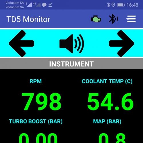
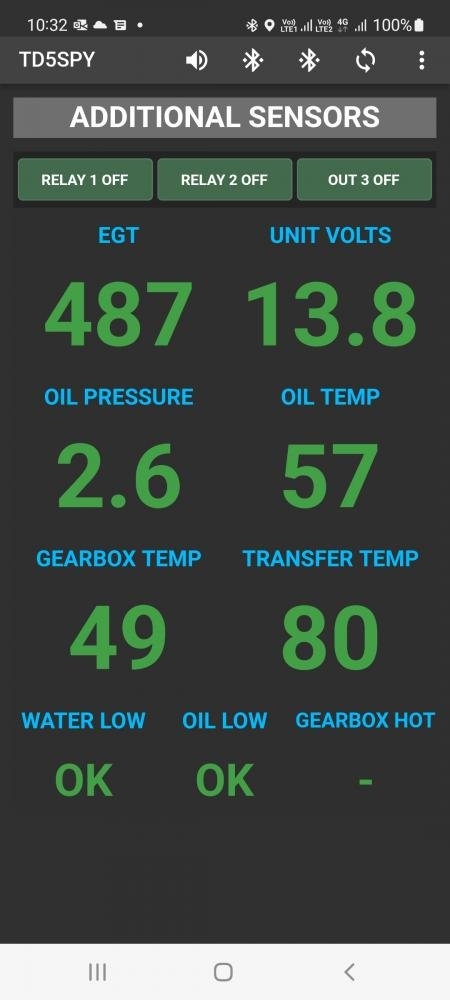
Open the TD5SPY application, go to System Settings, General Settings and select Mode to (TD5SPY + allSPY). Go back one level and then to allSPY Settings. Configure as below:
-
Download Sensor Tables: OFF
-
Emulate Removed Switches: ON
-
Enable Coolant Buzzer: ON
-
Invert Switch (1, 2 3): OFF
-
Sensor 1: OIL TEMP
-
Sensor 2: TRANSFER OIL TEMP
-
Sensor 3: GEARBOX OIL TEMP (Auto gearbox only)
-
Sensor 4: OIL PRESSURE
-
Sensor 5: NONE
-
Switch 1: OIL PRESSURE SW
-
Switch 2: NONE
-
Switch 3: COOLANT LEVEL SW
-
Go back one level and then to TD5SPY Data Adjusters. Set Pressure Sensor Range to 100PSI (7 bar)
-
Close the application completely, turn on the ignition and then restart the application. Wait for the TD5SPY and allSPY units to be listed in the BLUETOOTH CONNECTION list. Click on STOP SCAN button. Click on the TD5SPY entry in the list to connect to the TD5SPY. Once connected, scroll back to the list and click on the allSPY entry to connect to the allSPY. Both units should now be connected and displaying data.
-
Check the operation and positioning of the Coolant Level sensor. Secure at a suitable level using epoxy glue.
This Resource has been viewed 390 times.